Brute force is usually not the best approach when trying to understand physical phenomena. Physical systems are nothing but a collection of particles. In order to study how these particles interact with each other, theorists calculate the time-evolution of the whole ensemble. As the number of particles increases, calculations become not plausible. In this context, defining clever shortcuts may be the only way to study real systems. Columbia researchers have established a new theoretical framework that calculates the conditions under which a light burst is emitted by an array of atoms – a structure used in quantum computers. They found that they can predict whether the high intensity light pulse will be emitted by looking at the first moments, thus circumventing the need of solving for the whole time evolution.
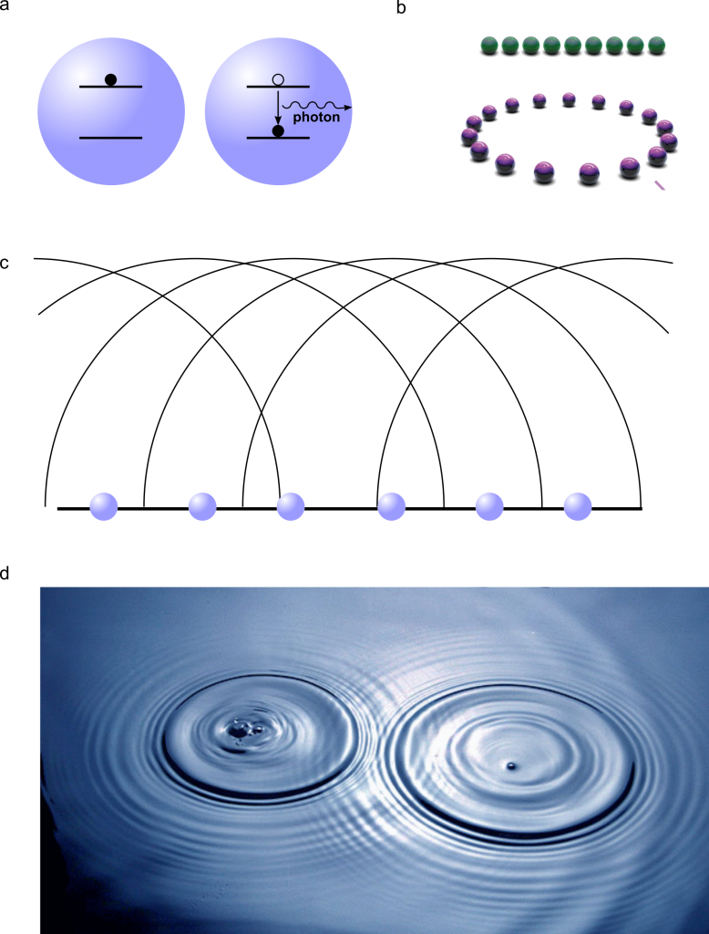
Spontaneous light emission is responsible for most of the light that we see. Examples of spontaneous emission are fireflies and the bioluminiscent bay in Puerto Rico. The physical mechanism responsible for spontaneous emission is sketched in Fig. 1a: the emitter (an atom that can be in two different energy states) is excited to a higher energy state, for example by external light. From that excited state, it spontaneously decays to a lower energy level, releasing the energy difference between the two states as a photon, i.e., as light. This is a purely quantum-mechanical process that cannot be explained by classical physics.
If multiple atoms are placed far away from each other, they act as independent units. When relaxing, they emit photons at an intensity that is proportional to the number of atoms present in the system. However, if the distance between the atoms is very small, a phenomenon called Dicke superradiance occurs.
When the atoms are very close, they interact with each other. As a result, the system as a whole cannot be regarded as the sum of many individual entities but rather as a collective system. Imagine many atoms close together forming an array, an ordered structure. External light will excite one of them, but there is no way to determine which atom within the array is the one that is excited. Effectively, all atoms are excited and not excited at the same time, the same way that Schrödinger’s cat is dead and alive at the same time. In quantum mechanics this phenomenon is called superposition. When one of the atoms relaxes, the full atomic array decays as a whole and a photon is emitted in a particular direction.
If an excited atom is isolated, there is no reason why it should emit a photon in a particular direction. However, in a coupled atomic array, constructive and destructive interference creates what are called bright and dark channels. To understand this concept, we only need a lake and a handful of rocks. When a rock is thrown into a lake, it creates a circular pattern around it by emitting a wave that travels in all the possible directions. However, if one throws many rocks close to each other into the lake, the resulting wave does not travel in all possible directions: the waves from the individual rocks interfere. Some directions will not have waves due to individual waves traveling in opposite directions (destructive interference) and the wave pattern will result from the constructive interference of the individual waves (see Fig. 1c,d). That’s exactly what happens in the atomic array: a photon – which is a quantum object and therefore can behave as a particle as well as a wave – is emitted from each atom in all possible directions, but most of those photons interfere destructively and only a few of them survive, and those constitute bright channels.
Now let’s think about the second event of photon emission. When the atoms are far away from each other, each photon would be emitted in a random direction. Nevertheless, in an atomic array, the fact that the first photon is radiated along a particular direction makes it more likely for the second photon to be radiated in that same direction. It’s like an avalanche: once the first snow has started moving down along a path, the rest of the snow follows. Once the first photon is emitted along a particular direction, the next photons follow. And that creates the superradiant burst, a high intensity pulse of light.
Theoretical calculations of superradiance in systems of many atoms are not possible due to the complexity of the calculation – the computer memory and time needed are both prohibitive. What Masson and colleagues found is that, by looking at the first two photons, one can already know if there is going to be a superradiant burst. They can anticipate if the avalanche is going to happen. This means that the early dynamics define the nature of the light emission, and a calculation of the whole time-evolution is not necessary.
Since the distance between the atoms dictates the emergence of superradiance, one may ask whether the arrangement of the atoms plays any role. Before Masson’s work, the understanding in the field was that atomic chains and rings behave differently. In an atomic chain, the two atoms at the end are different from those in the middle, since the atom at the edge has only one partner whereas the one in the middle has two. On the other hand, in a ring, all the atoms have the same environment (see Fig. 1b). And this is certainly true for a system with very few atoms. But thanks to the authors’ theoretical approach, it is now possible to include many atoms in the calculation. And they found that, despite the atoms’ arrangement, superradiance occurs equally in chains and rings when the number of atoms is very high. The reason is that, for structures with several atoms, the influence of the two placed at the end of the chain is washed out by the effect of the many atoms located in the middle. Moreover, they also found that atoms can exhibit superradiance at much larger distances than expected.
Atomic arrays are used in atomic clocks, in GPS technology, and quantum computers. In quantum technologies, each atom is used as a bit, the unit of information – it represents a 1 or a 0 depending on if it is excited or relaxed. A byte contains eight bits. As a reference, Figure 1 contains 6000000 bytes. The common belief is that interactions between the atoms and the environment produce information loss with respect to a pure, isolated system. However, Masson and Asenjo-Garcia show that interactions between the atoms results in their synchronization, producing a coherent, high intensity light burst.