Where does water actually come from? Most people would say, from the tap. While this certainly is true, scientists are – fortunately I would say, unfortunately my significant other might say – not like most people. They want to know more.
Before answering this question we should step back and ask, what is water? Water is a molecule, H2O. That means it consists of one oxygen atom, O, and two hydrogen atoms, H2. One way to produce water is to mix hydrogen and oxygen and ignite it. While on earth this can easily be done, on a cosmic scale initiating the reaction is far more complex. The biggest problem is that cosmic space is cold. Like, really cold. The official record for the coldest temperature measured on earth is held by the arctic Vostok Station with −128.6 °F (−89.2 °C). In comparison, diffuse dense clouds, common cosmic structures where a lot of cosmic chemistry happens, have temperatures of -441.7°F to -279.7°F (-263.2°C to -173.2°C). Anybody who has ever tried to cook but forgot to turn on the stove knows that for chemistry to happen, heat often has to be supplied, like through the flame in the above experiment. So, how can chemistry happen in the coldness of space?
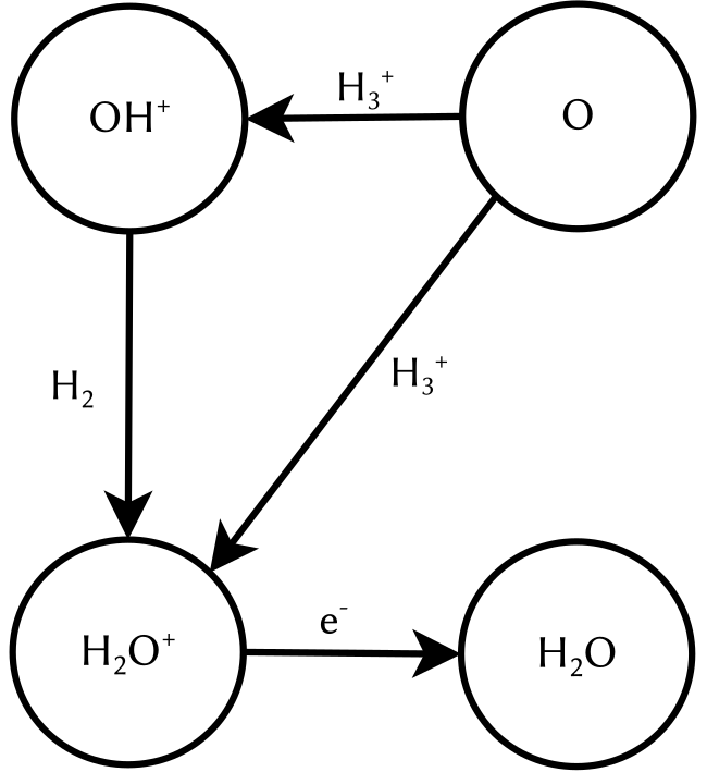
The key to understanding this lies in the state of matter of cosmic gas. On earth, matter is mostly electrically neutral. That means, it contains exactly the same number of positively and negatively charged particles which therefore cancel each other out. To electrostatically charge an object, we have to actively make an effort, think of rubbing a balloon against your hair. This is not true for the universe in general. Actually, most matter in space is not neutral but charged. One notable example is the molecular ion H3+, a molecule consisting of three hydrogen atoms which are missing one electron, leading to a singly positively charged ion. Charged molecules can undergo reactions which are not possible for their neutral counterparts. For example, they react at temperatures at which their neutral counterparts do not react. In chemistry charged molecules are called radicals and are widely known for having a bad influence on your health. So stay away from cosmic clouds to avoid wrinkles! One reaction network starts with the reaction of atomic oxygen O with H3+. In a first step, two outcomes are possible: either they react to OH+ and H2 which in a second step reacts to H2O+ which subsequently neutralises, or they directly react to H2O+ and H before undergoing the neutralisation. Until recently, little was known about which of the two outcomes was more likely. Therefore, astronomical modelling assumptions had to be made. A precise knowledge of the pathway of the reaction network shown in figure 1 is especially interesting for interstellar regions in which the interstellar OH+ can be destroyed before reacting to H2O+. Here the direct reaction is the only efficient way of forming water, since potentially every intermediate product can undergo reactions not resulting in H2O+, therefore less steps directly increase the reaction yield.
This gap of knowledge was filled by Hillenbrand and colleagues, who accurately measured the reaction O + H3+ for both possible outcomes and therefore were able to give the ratio between them. But wait, didn’t we just learn that for the cosmic area of interest, this reaction takes place at highly unpleasant freezing temperatures? How on earth can this be reproduced on earth in the laboratory while still being able to control the setup? For this, the scientists came up with a nice little trick. On a microscopic level, the temperature of an object can be linked to the velocity of the particles it is made up of. Hotter particles move faster, colder ones move slower. If packed densely together, they constantly hit each other and change their direction of movement, leading to a constant vibration of the whole particle cloud. And the stronger the vibrations, the hotter they are.
This phenomenon was first discovered in 1827 by the Scottish physicist Robert Brown and linked to their temperature in the PhD thesis of Albert Einstein in 1905. The scientists made use of this phenomenon to study the reaction with “cold” reactants without actually cooling them down. Instead of mixing gases of cold O and H3+ together, they created two directed particle beams and let them overlap so the reaction could take place. Even though the beams were produced at room temperature and their individual velocity was quite high, the velocities of the beams relative to each other could be controlled to be very small. Think of driving on the highway and passing another car: You may be travelling at a speed well above 60 mph, corresponding to over 5200 feet per minute. Still, it can actually take you multiple seconds to fully pass a vehicle 10 feet long or more if you are not driving much faster than it, therefore having a low relative speed. And as we just learned, a small velocity corresponds to a low temperature.

To study the reaction the scientists used the setup shown in figure 2. They used two ion sources to produce either a beam of H3+ or O- ions. Since the experiment requires neutral oxygen atoms, the negatively charged O- ions are first neutralised by a laser, which kicks away the additional electron. These two beams are then overlapped in an interaction region allowing the chemical reaction to take place. Varying the relative velocity of the beams, corresponding to varying the temperature at which the reaction takes place, it can be studied over a broad range of temperatures, ranging from close to absolute zero to more than 1000°F.
Using this setup they could measure the so-called branching ratio, meaning the ratio of the outcomes H2O+ to OH+, over a wide temperature range. For low temperatures they found a ratio close to 1:1, whereas for higher temperatures only 20% of the reactions resulted directly in H2O+. In astrochemical models over the whole temperature range a fixed ratio of 30:70 was used, originating from a single measurement at room temperature, which was found to be not true. This implies that the frequently used model underestimates the production of water in cold interstellar regions and has to be adapted.