Dedicated readers know our project uses motor-controlled cables attached to a pen to provide rehabilitation of fine motor skills. These cables are able to provide feedback, such as guiding the user through specific motions or simulating “walls” they will be unable to cross with the pen. Cables are ideal for this application because the driving motors do not need to be mounted to the user, unlike with “arm master” designs that resemble exoskeletons and affect the limb directly.
“However, cable mechanisms also have some drawbacks, including the unilaterality of the cables which leads to the necessity of having n+ 1 cables to suitably constrain n degrees of freedom (DOFs)” . ~Source
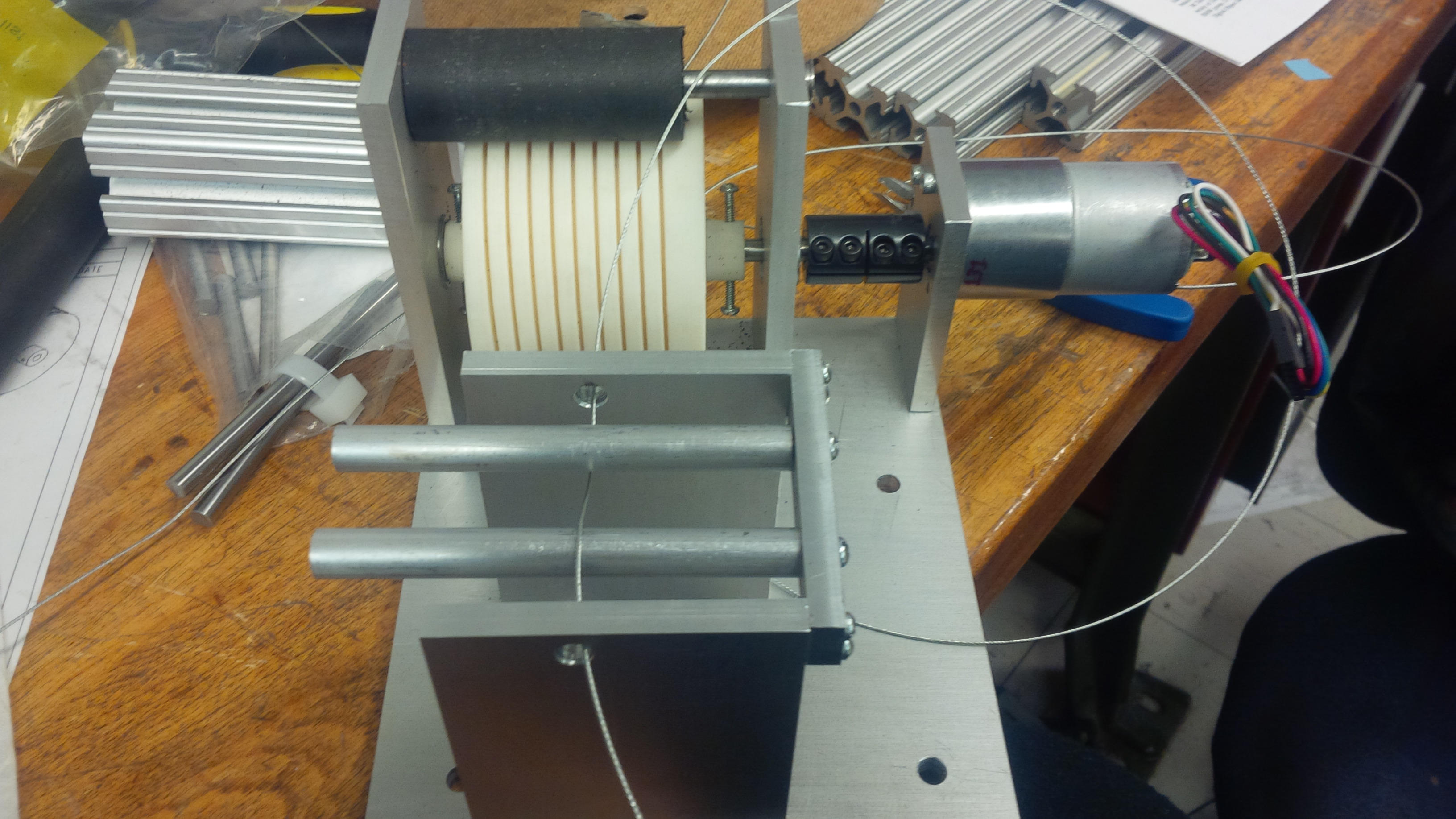
A mostly assembled spool. The strain gauge is placed on a third crossmember in between the two shown.
Basically, if we want to provide haptic feedback (simulating forces, walls, and so on) in two dimensions, we need to attach three cables to the pen, with a motor to control each one. This is because cables cannot push, only pull!
The keystone of this project is providing “null force.” This means keeping the cables barely taut. The goal is to have as little tension as possible while not allowing any slack. If this is accomplished, the user can move anywhere without feeling resistance. Then, when the pen crosses a virtual wall, we can raise the tension in one or more of the cables to simulate a collision.
Previously, we tried to detect tension by using current sensors. A motor attempting to turn at a constant rate will draw more current when encountering resistance. If the motor draws significantly more current pulling in the cable than playing it out, we can tell that the user is exerting tension on the cable. Unfortunately, the current sensors produced very noisy signals. Worse, they could not detect the tension when the motors were still because no current flows through an idle motor! As a consequence, we had to oscillate the motors back and forth very quickly even when the user was not moving the pen, in order to know the tension in the cable at all times.
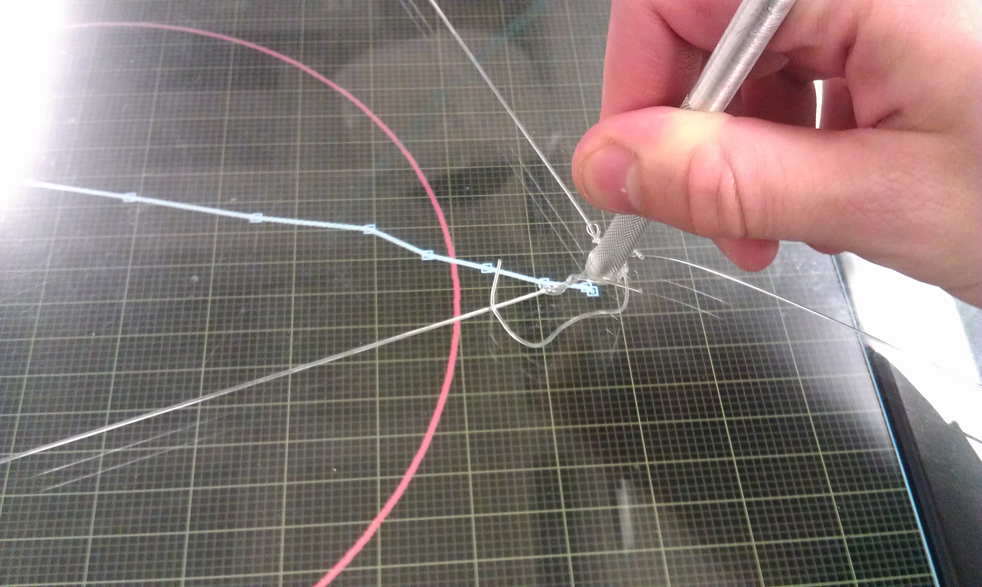
We now use strain gauges to more directly measure the tension. This required machining an assembly to transfer the tensile force into a lateral force to bend a bar with the strain gauge attached. Imagine you and a friend are each holding one end of a long jump rope. When you stand close to each other, the rope is slack on the ground. But if you move apart and pull, it leaps into the air! If you mounted a strain gauge on a bar above the rope when it is slack, you can measure the upward force when it is taut!
Working user interface with null force control!
By doing this with three motors, we have successfully implemented force control in two dimensions. We can simulate arbitrary boundaries and resist the user when he or she tries to move the pen beyond them. To make these effects more obvious to the user, we have assembled the cable system above a screen displaying the boundaries and tracing the pen’s position as it moves. We have also added auditory feedback to provide impact sounds when a collision occurs.
Our project will be on display in Lerner Hall this Thursday afternoon! Come see it and ask us all your burning questions!