Hydroponic systems have existed for centuries, providing an alternative agricultural method to soil-based growing for large crop yields. Recently, hydroponic systems have attracted increased attention from the home grower market, as they provide a way to grow plants easily indoors, thereby allowing individuals living in urban environments to grow their own fresh produce. Our system would prove highly attractive to this emerging consumer market, as we plan to construct a fully automated, inexpensive, and compact hydroponic system. Using simple construction methods and easily available components, we will create a streamlined hydroponic system that will remove the hassle of manual hydroponic systems that require frequent adjustments.
As a group, it was agreed upon that a clear plastic (acrylic) would be desired for the majority of the device, so the interior is visible for the final expo. This is an aesthetic choice, and in reality is not optimal for a hydroponic system, due to the potential for algae growth. If this product were made for market we would use opaque injection molded plastic instead of acrylic and ABS for our plastic parts. Acrylic, however, satisfied several of our design requirements, including satisfactory strength and ease of fabrication. Additionally, due to this project being a budget constrained design, having the necessary acrylic free and available played a role in the decision as well.
As mentioned earlier, we settled on an NFT hydroponic system. The bare essentials of a NFT system are: a water reservoir (> 3 gallons), water pump, plant channel, and controls for any electronics (Arduino). For full automation we are also including a light fixture, pH and electrical conductivity probes, peristaltic pumps (to control addition of plant nutrients and pH up/down), an air pump, temperature sensor, and heating element.
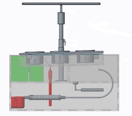
The design is broken down into 5 separate elements: 1st water reservoir, 2nd reservoir, plant channel, electronics chamber, and a lighting fixture. The plant channel consists of an acrylic rectangle, with a 2.5 degree angled base. There are three 2” holes for plant cages spaced 3” apart. The flanges on the top of the channel, are designed so it can rest on top of the water reservoir.
The reservoir of the herb garden has a few design requirements. Due to evaporation and water consumption we determined it must be able to hold 3 gallons of water. The second reservoir accounts for the evaporation, which is only 9 “W X 8″ D x 5” H. with a float switch to continually replace evaporated/used solution. The light assembly will be 3d printed and will allow for manual height adjustment. Finally, the electronics location should be above the water reservoir to minimize the risk of moisture damaging the electronics. From these requirements, and L shaped reservoir was chosen. The top half of the L is where the channel will rest, allowing water to flow through the channel, and fall back down into the main reservoir. The main water reservoir consists of a 19.5” W x 13” D x 10” H. with the missing portion from the L profile being a 19.5” W x 8” D x 5” H rectangle.
The final acrylic component is the electronics mount, which is the missing portion from the L profile, measuring 10” W x 8” D x 5” H. This section is attached with a magnetic clasp to the main reservoir. Within the electronics mount is the brain for the apparatus, as well as all the other components mentioned previously.
These acrylic enclosures will be made by laser cutting the unfolded boxes profile in 0.25” acrylic, then heat bending this piece to form the desired shape. It should be noted CAD drawings were made for 2 types of fabrication for the box. Heat bending is preferred, but if that proves too difficult, the laser cutter will be used to cut finger joints and bond them with epoxy. This has already been proven to be watertight through experimentation, while the heat bending technique is a newly found option.
As mentioned, there are several components within the electronics mount. This section has been placed directly above the main reservoir, so we can easily monitor and maintain the plants food supply. Here we have holes cut for direct access with the pH, EC, and temperature probes, with nutrient reservoirs that will be controlled with 3 peristaltic pumps to adjust pH and electrical conductivity. The pumps are bought off the shelf, and are mounted in a 3D printed ABS chamber. This chamber is fitted with 1/16” tubing sealed with 1/16” NPT press-fit tube fittings. This leaves the pump to apply as little as a single drop of solution at a time.
Other features that will be in the electronics mount are 4 LED lights, which will indicate when it is time to refill the main reservoir, or any of the nutrient/pH solutions. To activate these LED indicators we will use a simple circuit that will act as a water level. The LED will be triggered when the circuit is open, which occurs when it is out of water.